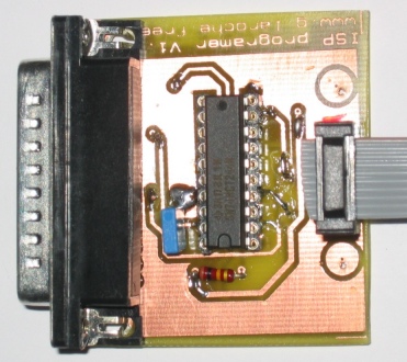
If you are just getting into microcontrollers there's alot to know as you have likely found out. There's alot of good online tutorials for the Atmel AVR's and chances are you have see a few of those by now. I recently got into microcontrollers and didn't know jack about it. I wanted to have some early success and get my AVR to do something cool (other than blink leds). I struggled through some terrible blog posts about how to control a common 16x2 LCD with the popular H44780 driver. I had to combine and tweak code from 3 places to get it working.

Download Program At90s2313 With Arduino Board. Project s atmega8 & lcd 128*64. Microcontroller families to use on- chip flash memory for program.
Anyway, over the past couple months I figured it out and since no one else has this covered on Instructables, I thought I would share my approach and see if you can get some early successes which will keep you diving deeper in to geekery. There's an embedded video and pic of what this project will look like when you are done. Ok, So you have 16x2 LCD with the H44780 or equivalent driver. These LCD's basically have a display screen, typically with an LED backlight, and a PCB on the back which has the driver. Advanced Id Creator Crack Keygen Online. This driver makes our job really easy for controlling the LCD with a little $1.50 MCU. The Hitachi H44780 driver already knows all the characters in the alphabet plus some special symbols.
It also has settings we can choose like show/hide the cursor, among others. The trick is, the way we control this is by hitting different combinations of the pins with 5v (binary 1) or 0v (binary 0). We will do this really fast and the driver will lookup and display the letters we pick.
You can read a little more about the H44780 here When we write a message (character string) in the program, the compiler will compile these letters into the respective ASCII hex codes which means we don't need a font file like in the case of a POV or dot matrix. So, lets set up the LCD for the breadboard. To make the LCD easy to work with on the breadboard we will solder the male header to the LCD package. These LCD's typically have 14 data pins and 2 for the LED backlight. So you will snap off a 16 pin piece of header and solder it into each of the 16 holes. See the pics. So you maybe wondering how we are going to control 16 pins of a LCD with a 20 pin MCU.
Menu
- ✔ Actualizacion Del Programa Pack Free Mcboot Installer V2v
- ✔ Santa Olivia Carey Mobius
- ✔ Biology Of Plants Raven Pdf Rapidshare Library
- ✔ Canon Vixia Hr300 Manual Treadmill
- ✔ Ghosts Of Flatbush Hbo Sports Commentators
- ✔ [pc]stellaris Ita
- ✔ Erk Tha Jerk Thirds Eye View Zipper
- ✔ Psremote 2 5 1 Keygen Mac
- ✔ Free Windows 7 Theme Download
- ✔ Minimoog V Mac Cracks
- ✔ Karcher Vaporapid 1501 Manual Transfer
- ✔ Spf Se 8 0 Download Diya
- ✔ Free Download Program Best The Back Horn Rar Extractor